Getting to Khow NodeMCU Board
13176 Views |

NodeMCU V3 Board is a microcontroller board based on the open source Lua firmware. The firmware is designed for the ESP8266 ESP-12E WiFi module, making the board ideal for development and use as a IoT Applications. The advantage of this board is that It has a low price and developers can also write programmable controllers through ArduinoIDE, which is easy to develop programs to work with various sensors. There are also many examples of drivers on different websites to new learners as well.
Features of the NodeMCU V3 board
- Using an ESP8266 ESP-12E microcontroller
- Uses Tensilica Xtensa Diamond 32-bit processor.
- The board consumes approximately 70mA (when transmitting a continuous signal, approximately 200mA), while standby consumes less than 200uA.
- The various interface pins use a voltage of 3.3V.
- There is an antenna for WiFi built into the board.
- Communication standard 802.11 b/g/n
- WiFi frequency used: 2.4GHz, support WPA / WPA2 security system.
- There are 9 digital communication pins, which can be set as input or output (D0-D8 can be used as pins GPIO, PWM, IIC, etc.), each pin can receive and supply a maximum current of 12mA.
- There is 1 analog communication pin, which can only be assigned as input, with a resolution of 10 bits (0-1023).
- Transfer Rate can be set from 110-460,800bps
- Support UART/GPIO communication
- The size of Flash Memory is 16 megabytes (which is reserved by the bootloader program for 0.5 kilobytes).
- The size of SRAM is 64 kilobytes and the size of EEPROM is 512 bytes.
- Board size: Length 58 mm. Width 31 mm.
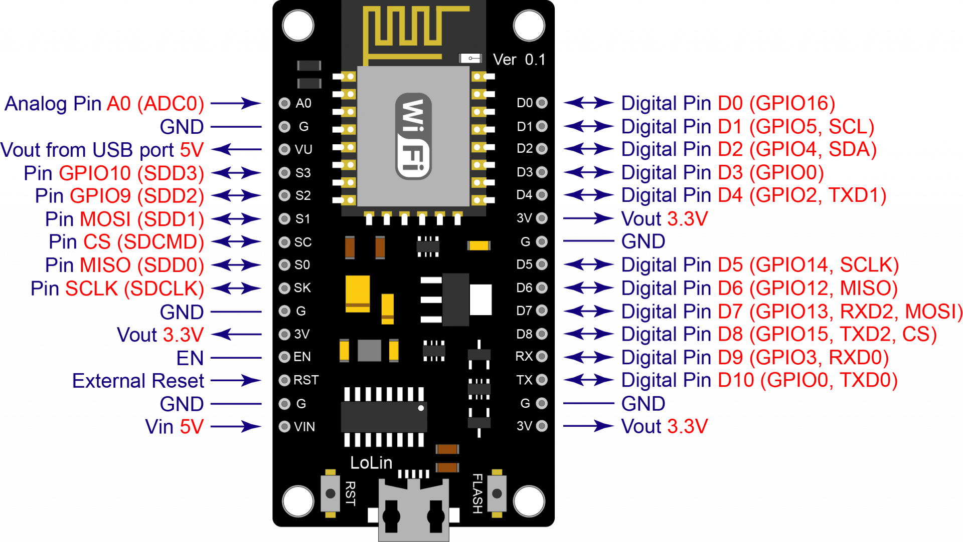
NodeMCU V3 board picture and various pins
1. Pin INPUT/OUTPUT in DIGITAL type has 11 pins in total, which can be set as Pin INPUT or Pin OUTPUT according to programming. This pin operates at a voltage of 3.3 VDC, a current that can be supplied and received is 12 mA. In addition, some pins can also be assigned special functions.2. Pin INPUT type ANALOG has the number of 1 pin(A0) which each pin has a maximum voltage of 3.3 VDC compared to ground. and has a resolution of 10 bits.
| Board Symbol | GPIO | Function | Detail |
| D0 | GPIO16 | Wake up | While Boot status is HIGH |
| D1 | GPIO5 | SCL | I2C |
| D2 | GPIO4 | SDA | I2C |
| D3 | GPIO0 | FLASH | Connected to the FLASH switch, it is not recommended to have a LOW state because it will prevent booting. |
| D4 | GPIO2 | BUILT-IN LED | It is not recommended to have a LOW state because it will prevent booting. |
| D5 | GPIO14 | SCLK | SPI |
| D6 | GPIO12 | MISO | SPI |
| D7 | GPIO13 | MOSI | SPI |
| D8 | GPIO15 | CS | SPI, it is not recommended to have a HIGH status because it will prevent booting. |
| RX | GPIO3 | RX | May be used as Input pin, while Boot status is HIGH |
| TX | GPIO1 | TX | May be used as Input pin, while Boot status is HIGH, it is not recommended to have LOW state because it will prevent booting. |
| A0 | ADC0 | Input Only | Analog Input Pin |
The table shows the position of the pins and their functions.
3. Vin pin is an external power supply pin. If power is supplied to this pin Do not supply power through the USB terminal.
4. Pin VU is a power supply pin 5 VDC by the voltage 5 VDC is obtained from the USB connector.
5. Pin Vout 3.3V is a positive power supply pin of 3.3 VDC, the maximum current about 500 mA.
6. Pin GND is the ground pin of the circuit.
How to install Driver of NodeMCU V3 Board on Windows OS (Only CH340 Board)
1.Download Driver CH341SER.EXE at https://www.futurekit.com/manualmicrobot
2. When the download is complete, install Driver by double-clicking the CH341SER.EXE file.
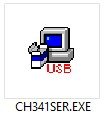
Driver program picture for CH340
3. Press INSTALL button to install Driver.
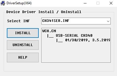
Picture of the installation process
4. When the installation is complete, A message will appear as shown in the picture, press the OK button and close the program.
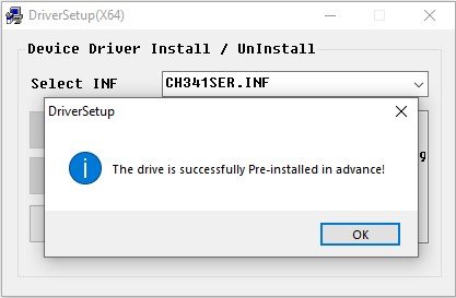
Picture when the installation is complete.
How to see Com Port connected to NodeMCU V3 board
1.Connect the NodeMCU V3 board to the computer.
2.Go to the Devices Manager section of your computer. (In case you can't find it (Right click on My Computer or This PC on the Desktop, then select Properties, you will notice the Devices Manager message, click it)
3.Observe the Ports (COM & LPT) as shown in the picture, it is USB-SERIAL CH340 (COM6), that is the Com Port location of Board Arduino on our computer. (Some machines may be different)

Picture showing Com Port in Devices Manager
?")