Learn to control the output pins with the UNO R3 Board
4452 Views |

UNO Board has 16 digital OUTPUT pins, all of which work at a voltage of 5 VDC.
Parts Requried :
- 1 x UNO board
- 1 x A/B type USB cable
- 1 x LED module board
- LED 5 mm. red, yellow, green, 1 each color
- 4 jumper cables
What is an LED bulb?
LED stands for Light Emitting Diode. It is a type of diode that can emit light. The LED is made of semiconductor type Gallium Asenide Phosphide (Galium Asenide Phosphide). which can emit more light than silicon diodes There are many types of LED such as Normal, Super Bright, Ultra Bright, etc., depending on the needs of the user that they need more or less brightness. The price will be high as well.

Electrical pictograms of the LED body and the actual figure.
Flashing light circuit test
For this test, Only UNO Board and USB cable will be used because we will use the LED connected to Pin 13 on the board as a display.
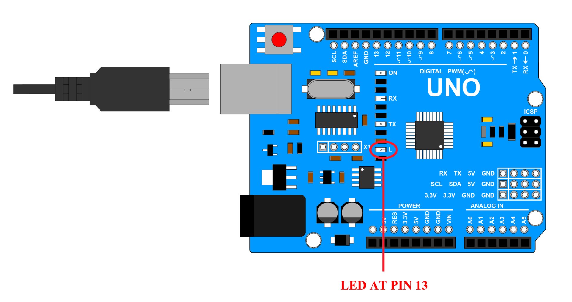
Picture of connecting USB cable to UNO board
The process of writing Flashing Lights Sketch
1.Open program Arduino IDE and write Sketch as shown in the example below. (No need to enter a comment)
void setup() { // This section is used to configure various settings. It will work when starting to supply power only once.
pinMode(13, OUTPUT); // set pin 13 as OUTPUT pin
}
void loop() { // This will be the working part. The program will continue to work in this section. until the power is not supplied
digitalWrite(13, HIGH); // set pin 13 to be HIGH (5 volts voltage comes out)
delay(1000); // Delay 1000 miliSecond for the program to execute the previous command
digitalWrite(13, LOW); // set pin 13 to LOW (no voltage output)
delay(1000); // Delay 1000 miliSecond for the program to execute the previous command
}
2.Connect UNO board to the computer. Then go to Tools and notice that Board has selected Arduino UNO or not and select COM Port that Board Arduino is connected to (each computer may show COM Port differently).
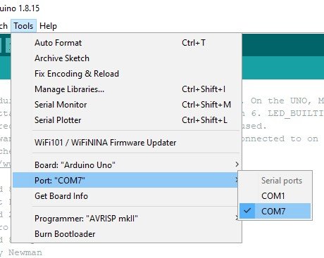
Image of selecting COM Port that UNO board
3.Then press the Upload button at the Shortcut menu, notice the status of the program. If it shows as shown below, Sketch has been uploaded to UNO board successfully. (in case of red Notice the error message. and edit)
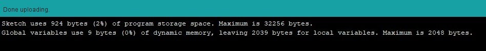
Image showing message when Sketch is uploaded successfully.
4.Observe that the LED on the UNO board will turn on and off intermittently. It will turn on for 1 second and turn off for 1 second alternately, indicating that the program is working properly. as we wrote (If you want to blink faster To reduce the number in the Delay command, but if you want to slow down the flashing. add numbers in the Delay command)
3 flashing lights circuit
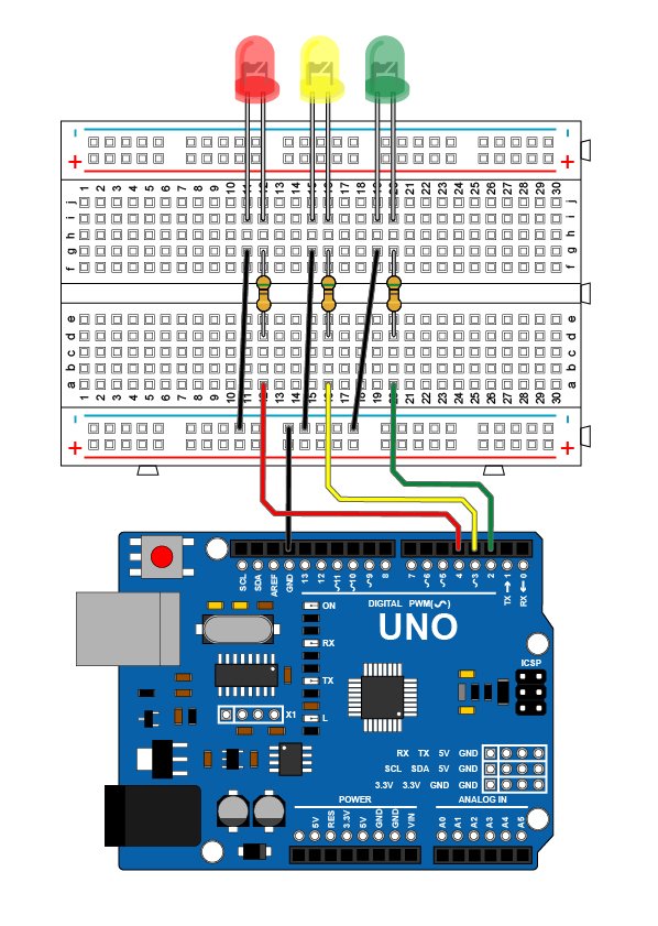
Connection diagram of 3 flashing lights

Connection diagram of 3 flashing lights (LED Module Board)
The process of writing a 3 blinking lights Sketch
1.Open program Arduino IDE and write Sketch as shown in the example below. (No need to enter a comment)
void setup() {
pinMode(2, OUTPUT); // set pin 2 as OUTPUT pin
pinMode(3, OUTPUT); // set pin 3 as OUTPUT pin
pinMode(4, OUTPUT); // set pin 4 as OUTPUT pin
}
void loop() {
digitalWrite(2, HIGH); // set pin 2 to be HIGH (with a voltage of 5 volts)
delay(500); // Delay 500 miliSecond for the program to execute the previous command
digitalWrite(2, LOW); // set pin 2 to LOW (no voltage output)
delay(500);
digitalWrite(3, HIGH); // set pin 3 to be HIGH
delay(500);
digitalWrite(3, LOW); // set pin 3 to LOW
delay(500);
digitalWrite(4, HIGH); // set pin 4 to HIGH
delay(500);
digitalWrite(4, LOW); // set pin 4 to LOW
delay(500);
}
2.For Sketch, you can write another way, as in the example.
void setup() {
pinMode(2, OUTPUT); // set pin 2 as OUTPUT pin
pinMode(3, OUTPUT); // set pin 3 as OUTPUT pin
pinMode(4, OUTPUT); // set pin 4 as OUTPUT pin
}
void loop() {
for (int i = 2; i <= 4; i++) { // set i equal to 2-4 and so on.
digitalWrite(i, HIGH); // set i to HIGH
delay(500);
digitalWrite(i, LOW); // set i to LOW
delay(500);
}
}
3.You can choose to use in item 1 or item 2, and then press Upload button at the Shortcut menu, wait until Done Uploading appears and notice that the UNO board LED will turn on and off from Pin 2, 3 and 4 continuously.

